The design of a bandpass filter (BPF) is governed by several critical parameters that define its performance and application suitability.
1.Center Frequency (f₀):The midpoint of the passband, the frequency the filter is designed to pass.
2.Bandwidth (BW):The range of frequencies allowed to pass, calculated as the difference between the upper (f_high) and lower (f_low) -3dB cutoff frequencies.
3.Insertion Loss:The signal power loss within the passband, ideally minimized.
4.Stopband Rejection/Attenuation:The amount of signal attenuation outside the desired passband, defining how well the filter blocks unwanted frequencies.
5.Passband Ripple:The maximum allowable variation in gain within the passband. A smaller ripple indicates a flatter, more uniform response.
6.Quality Factor (Q):The ratio of center frequency to bandwidth (Q = f₀ / BW). A high Q indicates a narrow, selective passband.
7.Order (n): Determines the filter's steepness or roll-off rate. A higher order provides a sharper transition between passband and stopband.
8.Impedance:The input and output impedance (typically 50Ω or 75Ω) must match the source and load to prevent signal reflections.
Additional considerations include power handling, size, and the choice of topology (e.g., Butterworth for flat response, Chebyshev for steeper roll-off, or elliptic for very high attenuation).
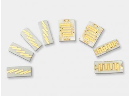
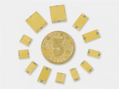
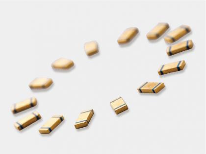
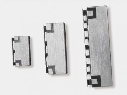
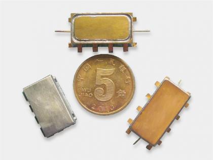
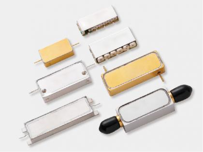
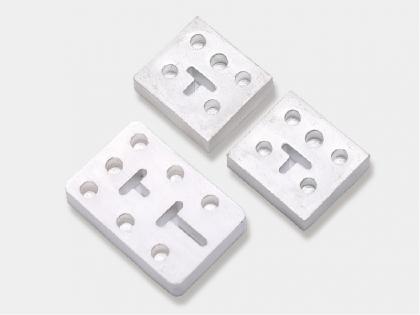
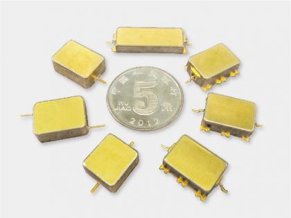
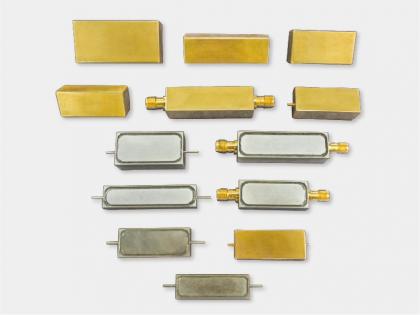
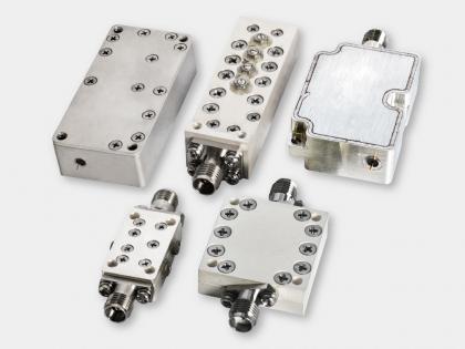
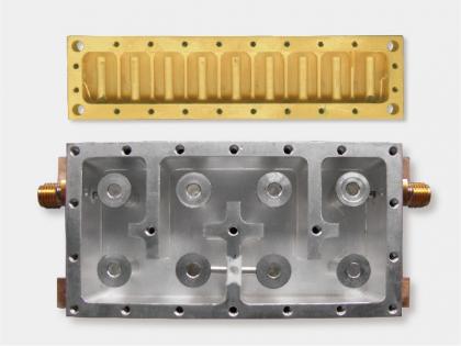
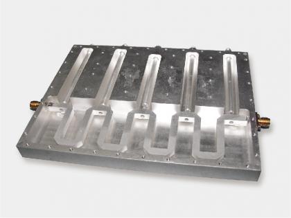
Yun Micro, as the professional manufacturer of rf passive components, can offer the cavity filters up 40GHz,which include band pass filter, low pass filter, high pass filter, band stop filter.
Welcome to contact us: liyong@blmicrowave.com

Address : Xisan Road, Mechanical and Electrical Industrial Park, No.767 Yulan Road, Hefei,Anhui.
Tel : +86-18855146875
Email : liyong@blmicrowave.com


Scan it