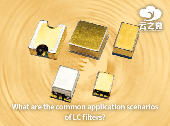
other
  • Standard vs Customized Filters: Which One Is Right for Your Project?
    When working on electronic signal processing, communication systems, or audio equipment projects, choosing between standard filters and custom filters depends on specific technical requirements, budget constraints, and performance needs. Here’s a comparative analysis of the two options:   1. Standard Filters (Off-the-Shelf Filters)   Ideal for: General signal processing needs, such as routine filtering, noise reduction, or frequency band selection.   ✔ Advantages:   Cost-effective – Mass-produced, making them more affordable.   Ready to use – No design lead time, speeding up project timelines.   Stable performance – Tested for common applications with reliable results.   Good compatibility – Typically adhere to industry-standard interfaces (e.g., SMA, BNC).   ✖ Disadvantages:   Limited flexibility – Fixed parameters like frequency response and stopband attenuation cannot be adjusted.   Performance constraints – May not meet high-precision or specialized application requirements.   Typical Applications:   Audio signal processing (low-pass, high-pass, band-pass filtering)   Radio communications (preselect filters, anti-aliasing filters)   Laboratory test equipment (standard frequency band filtering)    2. Custom Filters   Ideal for: Specialized frequency response requirements, harsh environments, or high-performance systems.   ✔ Advantages:   Customizable parameters – Precise design of cutoff frequency, roll-off slope, group delay, etc.   Optimized performance – Tailored to specific interference or signal characteristics (e.g., ultra-narrowband, steep transition bands).   Adapts to unique needs – Supports high-temperature, radiation-resistant, or miniaturized designs.   Integrated solutions – Can be embedded into system PCBs or combined with other functional modules.     ✖ Disadvantages:   Higher cost – Requires dedicated design, simulation, and debugging, significantly increasing development expenses.   Longer lead time – Design to delivery may take weeks or even months.   Supplier dependency – Future modifications or maintenance may require manufacturer support.   Typical Applications:   Military radar/electronic warfare (anti-jamming, ultra-wideband filtering)   Satellite communications (high-frequency, low-loss filtering)   Medical equipment (e.g., MRI signal processing)   High-precision instruments (quantum computing, astronomical observation)     Selection Recommendations: Choose standard filters if your project has common requirements (e.g., audio noise reduction, standard RF filtering) and off-the-shelf products meet your specifications. Opt for custom filters if: Standard products cannot meet your frequency response, size, or environmental requirements; Your system demands extreme performance (e.g., <0.1dB ripple); Deep integration with oth...
  • Can cavity band pass filters be used in space applications? If yes, what considerations are necessary?
    Cavity bandpass filters can be used in space applications, but they require special considerations due to the harsh space environment. Here are the key factors to address: 1. Material Selection & Thermal Stability Low Outgassing Materials: Space-grade materials (e.g., Invar, titanium, or specially coated aluminum) must be used to minimize outgassing in vacuum, which could contaminate sensitive optics or electronics. Thermal Expansion Control: The filter must maintain performance across extreme temperature swings (e.g.,150°C to +150°C). Materials with matched coefficients of thermal expansion (CTE) should be chosen to prevent mechanical deformation. 2. Vibration & Mechanical Robustness Must survive high launch vibrations (typically 10–2000 Hz, 10–20 G RMS). Reinforced structures or damping mechanisms may be needed to prevent microphonics or detuning. 3. Radiation Hardness Some dielectric or ferromagnetic materials can degrade under ionizing radiation. Radiation-resistant coatings or materials (e.g., alumina, sapphire) should be considered. 4. Vacuum Compatibility No organic adhesives that could outgas; instead, use brazing or welding. Avoid trapped volumes that could cause pressure differential issues. 5. Frequency Stability & Tuning Thermal shifts can detune the filter; temperature compensation (e.g., using dielectric rods with opposite CTE) may be required. Some missions may require tunable filters (e.g., piezoelectric actuators) for adaptability. 6. Insertion Loss & Power Handling Minimize loss (critical for weak signals in deep space comms). High-power applications (e.g., satellite transmitters) may need enhanced heat dissipation. 7. Testing & Qualification Thermal Cycling: Verify performance across mission temperature ranges. Vibration Testing: Simulate launch conditions per standards like NASA-STD-7003 or ECSS-E-10-03. Outgassing Tests: Meet NASA ASTM E595 or ESA ECSS-Q-ST-70-02. Example Space Applications Satellite communication (e.g., X/Ku/Ka-band filters). Deep-space probes (narrowband filters for high-selectivity comms). Earth observation (spectral filtering in hyperspectral imagers). Conclusion Cavity bandpass filters are viable in space but require rigorous design, material selection, and testing to ensure reliability. Custom solutions from space-qualified manufacturers (e.g., ESA/NASA-approved vendors) are often necessary. Yun Micro, as the professional manufacturer of rf passive components, can offer the cavity filters up 40GHz,which include band pass filter, low pass filter, high pass filter, band stop filter. Welcome to contact us: liyong@blmicrowave.com
  • The Importance of Custom RF Filters in IoT and 5G Technology
    The rapid expansion of IoT (Internet of Things) and 5G networks has increased the demand for highperformance RF (Radio Frequency) filters. Standard offtheshelf filters often fail to meet the unique requirements of modern wireless systems, making custom RF filters essential for optimal performance. Here’s why they are critical: 1. Spectrum Efficiency & Interference Mitigation 5G and IoT operate in crowded frequency bands (Sub6 GHz, mmWave, and licensed/unlicensed spectrums).   Custom filters precisely target desired frequencies while rejecting interference from adjacent bands, improving signal clarity.   Example: In massive IoT deployments, filters prevent crosstalk between thousands of connected devices.   2. Enhanced Signal Integrity & Low Latency 5G requires ultralow latency (<1 ms for critical applications like autonomous vehicles and industrial IoT). Custom filters minimize signal distortion and insertion loss, ensuring high data throughput.   Example: Edge computing devices rely on clean signals for realtime processing.   3. Miniaturization & Power Efficiency IoT devices demand compact, lowpower components.   Custom SAW (Surface Acoustic Wave) and BAW (Bulk Acoustic Wave) filters enable small form factors with high selectivity.   Example: Wearable health monitors use tiny, efficient filters to extend battery life.  4. Compliance with Evolving Standards Regulatory requirements (FCC, 3GPP, etc.) vary by region and application.   Custom filters ensure compliance with spectral masks, emission limits, and security protocols.   Example: Smart city sensors must avoid interfering with public safety bands.   5. FutureProofing Wireless Systems As 5G Advanced (5.5G) and 6G emerge, filters must adapt to higher frequencies (THz range) and dynamic spectrum sharing.   Custom designs allow upgrades without hardware overhauls.   Conclusion Custom RF filters are indispensable for optimizing IoT scalability, 5G reliability, and nextgen wireless innovation. By enabling interferencefree communication, lowpower operation, and regulatory compliance, they form the backbone of modern connectivity.   Yun Micro, as the professional manufacturer of rf passive components, can offer the cavity filters up 40GHz,which include band pass filter, low pass filter, high pass filter, band stop filter. Welcome to contact us: liyong@blmicrowave.com
  • What Is a Bandreject Filter and When Should You Use It?
    Band-Reject Filter (BRF) is a type of filter that allows most frequency signals to pass while strongly attenuating a specific frequency range (stopband). It functions opposite to a bandpass filter and is used to suppress interference or unwanted frequency components.     Key Applications   1. Interference Rejection: In communication systems, it eliminates noise or interference in specific bands (e.g., power-line hum, harmonic interference).   2. Signal Conditioning: In audio or RF systems, it removes spurious signals to improve signal-to-noise ratio.   3. Equipment Protection: Prevents strong interfering signals from damaging sensitive electronics (e.g., radar, medical devices).   4. Spectrum Management: In wireless communications, it avoids crosstalk between different frequency bands.      When to Use It?   A band-reject filter is ideal when a system has fixed-frequency interference and needs to preserve signals in other bands. Examples include removing 50Hz power-line noise or suppressing interference in a specific radio frequency band. Yun Micro, as the professional manufacturer of rf passive components, can offer the cavity filters up 40GHz,which include band pass filter, low pass filter, high pass filter, band stop filter.   Welcome to contact us: liyong@blmicrowave.com
  • How to test and validate the performance of cavity band pass filters in a lab setting?
    Testing and validating the performance of cavity bandpass filters in a lab setting involves several key measurements to ensure they meet specifications such as insertion loss, return loss, bandwidth, center frequency, rejection, and power handling. Below is a stepbystep guide: 1. Required Equipment Vector Network Analyzer (VNA) – For Sparameter measurements (S11, S21). Signal Generator & Spectrum Analyzer – Alternative if VNA is unavailable. Power Meter – For insertion loss verification. Power Amplifier & Dummy Load – For highpower testing (if applicable). Calibration Kits (SOLT/TRL) – For VNA calibration. Cables & Adapters – Highquality, phasestable RF cables. Temperature Chamber (if needed) – For thermal stability testing. 2. Preparation Calibrate the VNA up to the desired frequency range (e.g., 1–10 GHz) using SOLT (ShortOpenLoadThru) calibration. Connect the filter properly (ensure proper mating with minimal cable movement). Allow warmup time for the filter (especially for highQ cavities, as temperature affects performance). 3. Key Measurements a) Frequency Response (S21 – Insertion Loss & Bandwidth) Measure S21 (transmission) across the frequency range. Identify: Center frequency (f₀) – Where insertion loss is lowest. 3 dB bandwidth – Frequency range where loss is ≤3 dB from peak. Insertion loss (IL) – Minimum loss at f₀ (should be as low as possible, e.g., <0.5 dB). Shape factor – Ratio of 60 dB BW to 3 dB BW (indicates steepness of skirts). b) Return Loss / VSWR (S11 – Input Match) Measure S11 (reflection) to check impedance matching. Return loss should be >15 dB (VSWR <1.5) in the passband. Poor return loss indicates mismatches (e.g., improper coupling). c)OutofBand Rejection Measure stopband attenuation at specified frequencies. Check for spurious responses (unexpected passbands). Verify rejection meets specs (e.g., >60 dB at ±500 MHz from f₀). d) Group Delay (Phase Linearity) Use VNA’s group delay measurement (derivative of phase). Should be flat in the passband for minimal signal distortion. e)Power Handling (if applicable) Apply highpower signal (CW or pulsed) near f₀. Monitor S21 before/after for degradation (indicating arcing or heating). Measure temperature rise (for highpower filters). f) Thermal Stability (for critical applications) Place filter in a temperature chamber. Measure frequency drift and IL variation over temperature (e.g., 40°C to +85°C). 4. Validation Against Specs Compare results with datasheet or design goals: Passband ripple (should be minimal, e.g., <0.2 dB). Bandwidth (must meet required 3 dB or 1 dB BW). Rejection (must meet required attenuation in stopbands). Power handling (no degradation at rated power). 5. Troubleshooting Common Issues High insertion loss? → Check for poor coupling or conductor losses. Poor return loss? → Verify proper impedance matching (tuning screws may need adjustment). Asymmetric response? → Possible manufacturing defects (misaligned resonators). Fre...
  • How to Design a Custom Bandpass or Bandreject Filter for Specific Frequency Ranges?
    How to Design a Custom Bandpass or Bandreject Filter for Specific Frequency Ranges? Steps: 1.Define Parameters: Choose type (BPF/BRF), center frequency (F0), bandwidth (BW) or cutoff frequencies (F1、F2), filter order, and attenuation requirements. 2. Select Topology: Passive: RLC circuits (simple but load-sensitive). Active: Op-amp + RC (e.g., Sallen-Key, multiple feedback). Digital: FIR/IIR (requires DSP). 3.Calculate Components: 4.Simulate & Verify: Use SPICE or Python (SciPy) to simulate frequency response and tweak component values. 5. Prototype & Test: Account for component tolerances, parasitics, and optimize performance. Yun Micro, as the professional manufacturer of rf passive components, can offer the cavity filters up 40GHz,which include band pass filter, low pass filter, high pass filter, band stop filter. Welcome to contact us: liyong@blmicrowave.com
  • What Are the Benefits of Using a Customized Filter for Your RF Application?
    Customized RF filters offer three key advantages over off-the-shelf solutions. First, they provide exact frequency response tailoring - precise control over passband/stopband ranges, rejection slopes, and insertion loss - ensuring optimal interference suppression for your specific application. Second, they enable superior physical integration, whether for extreme environments (high temp/power), compact layouts, or multi-band systems where generic filters fall short.  Finally, while requiring higher initial investment, they deliver long-term value through enhanced reliability, perfect system compatibility, and reduced need for additional filtering stages - particularly critical for 5G, defense, and aerospace applications where performance margins matter most.   Yun Micro, as the professional manufacturer of rf passive components, can offer the cavity filters up 40GHz,which include band pass filter, low pass filter, high pass filter, band stop filter.   Welcome to contact us: liyong@blmicrowave.com
  • How to Design a Bandreject Filter for High-Frequency Applications?
    Designing a bandreject filter (also called a notch filter) for high-frequency applications requires careful consideration of frequency range, rejection depth, circuit topology, and real-world component behavior at RF/microwave frequencies. Below is a structured approach to designing such a filter.   1. Define Key Specifications Center frequency (f₀): The frequency to be rejected (e.g., 2.4 GHz for Wi-Fi interference). Bandwidth (BW): The range of frequencies to attenuate (e.g., ±100 MHz around f₀). Rejection depth: Desired attenuation in the stopband (e.g., >30 dB). Impedance matching: Typically 50Ω (RF systems) or 75Ω (video/telecom). Insertion loss in passband: Minimize signal loss outside the rejected band. 2. Choose a Filter Topology A. LC Resonant Circuits (Suitable for MHz to Low GHz) Series LC Notch: Blocks signals at resonance (high impedance at f₀). Best for narrowband rejection. Parallel LC Notch: Shunts unwanted signals to ground at f₀. Useful in shunt-stub configurations. Limitations: Parasitic capacitance/inductance affects performance at high frequencies. B. Transmission Line / Distributed Filters (GHz Range) Quarter-wave (λ/4) Stub Filters: Open or short-circuited stubs create impedance mismatches at f₀. Example: A parallel open stub rejects signals at λ/4 resonance. Defected Ground Structure (DGS): Etched patterns on PCB ground plane act as a bandstop element. Advantage: Better performance in microwave frequencies (e.g., 5G, radar). C. Active Notch Filters (For Lower Frequencies, <100 MHz) Uses op-amps with feedback networks (e.g., Twin-T, Wien bridge). Limited by op-amp bandwidth at higher frequencies.   3. High-Frequency Component Selection Inductors (L): Use air-core or high-Q RF inductors to minimize losses. Avoid ferrite cores at GHz (high parasitic capacitance). Capacitors (C): NP0/C0G ceramic or RF capacitors for stability. Minimize equivalent series inductance (ESL). PCB Layout Considerations: Short traces to reduce parasitic inductance. Use ground planes and controlled impedance lines.   4. Design Example (LC Parallel Notch Filter for 2.4 GHz) Calculate L & C for resonance at f₀: Example: For 2.4 GHz, choose L = 2.2 nH, then C ≈ 2 pF. Place the LC in shunt (parallel) with the signal path. At 2.4 GHz, the LC tank creates a low-impedance path to ground, attenuating the signal. Simulate & Optimize (e.g., in Keysight ADS or Ansys HFSS): Account for PCB parasitics (trace inductance, via effects).   5. Validation & Tuning  Measure with a Vector Network Analyzer (VNA): Check S21 (transmission) for rejection depth. Verify S11 (reflection) for impedance matching. Adjustments: Fine-tune L/C values or stub lengths for optimal performance. Key Challenges in High-Frequency Design Parasitics: Stray capacitance/inductance shifts f₀. Component tolerance...
1 2 3 4 5

A total of 5 pages

Subscribe to Our Newsletter
Sign up to our newsletter for the Microwaves & RF.

Leave A Message

Leave A Message
If you are interested in our products and want to know more details,please leave a message here,we will reply you as soon as we can.

Home

Products

skype