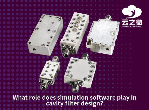
other
  • The Importance of Custom RF Filters in IoT and 5G Technology
    The rapid expansion of IoT (Internet of Things) and 5G networks has increased the demand for highperformance RF (Radio Frequency) filters. Standard offtheshelf filters often fail to meet the unique requirements of modern wireless systems, making custom RF filters essential for optimal performance. Here’s why they are critical: 1. Spectrum Efficiency & Interference Mitigation 5G and IoT operate in crowded frequency bands (Sub6 GHz, mmWave, and licensed/unlicensed spectrums).   Custom filters precisely target desired frequencies while rejecting interference from adjacent bands, improving signal clarity.   Example: In massive IoT deployments, filters prevent crosstalk between thousands of connected devices.   2. Enhanced Signal Integrity & Low Latency 5G requires ultralow latency (<1 ms for critical applications like autonomous vehicles and industrial IoT). Custom filters minimize signal distortion and insertion loss, ensuring high data throughput.   Example: Edge computing devices rely on clean signals for realtime processing.   3. Miniaturization & Power Efficiency IoT devices demand compact, lowpower components.   Custom SAW (Surface Acoustic Wave) and BAW (Bulk Acoustic Wave) filters enable small form factors with high selectivity.   Example: Wearable health monitors use tiny, efficient filters to extend battery life.  4. Compliance with Evolving Standards Regulatory requirements (FCC, 3GPP, etc.) vary by region and application.   Custom filters ensure compliance with spectral masks, emission limits, and security protocols.   Example: Smart city sensors must avoid interfering with public safety bands.   5. FutureProofing Wireless Systems As 5G Advanced (5.5G) and 6G emerge, filters must adapt to higher frequencies (THz range) and dynamic spectrum sharing.   Custom designs allow upgrades without hardware overhauls.   Conclusion Custom RF filters are indispensable for optimizing IoT scalability, 5G reliability, and nextgen wireless innovation. By enabling interferencefree communication, lowpower operation, and regulatory compliance, they form the backbone of modern connectivity.   Yun Micro, as the professional manufacturer of rf passive components, can offer the cavity filters up 40GHz,which include band pass filter, low pass filter, high pass filter, band stop filter. Welcome to contact us: liyong@blmicrowave.com
  • What Is a Bandreject Filter and When Should You Use It?
    Band-Reject Filter (BRF) is a type of filter that allows most frequency signals to pass while strongly attenuating a specific frequency range (stopband). It functions opposite to a bandpass filter and is used to suppress interference or unwanted frequency components.     Key Applications   1. Interference Rejection: In communication systems, it eliminates noise or interference in specific bands (e.g., power-line hum, harmonic interference).   2. Signal Conditioning: In audio or RF systems, it removes spurious signals to improve signal-to-noise ratio.   3. Equipment Protection: Prevents strong interfering signals from damaging sensitive electronics (e.g., radar, medical devices).   4. Spectrum Management: In wireless communications, it avoids crosstalk between different frequency bands.      When to Use It?   A band-reject filter is ideal when a system has fixed-frequency interference and needs to preserve signals in other bands. Examples include removing 50Hz power-line noise or suppressing interference in a specific radio frequency band. Yun Micro, as the professional manufacturer of rf passive components, can offer the cavity filters up 40GHz,which include band pass filter, low pass filter, high pass filter, band stop filter.   Welcome to contact us: liyong@blmicrowave.com
  • How to test and validate the performance of cavity band pass filters in a lab setting?
    Testing and validating the performance of cavity bandpass filters in a lab setting involves several key measurements to ensure they meet specifications such as insertion loss, return loss, bandwidth, center frequency, rejection, and power handling. Below is a stepbystep guide: 1. Required Equipment Vector Network Analyzer (VNA) – For Sparameter measurements (S11, S21). Signal Generator & Spectrum Analyzer – Alternative if VNA is unavailable. Power Meter – For insertion loss verification. Power Amplifier & Dummy Load – For highpower testing (if applicable). Calibration Kits (SOLT/TRL) – For VNA calibration. Cables & Adapters – Highquality, phasestable RF cables. Temperature Chamber (if needed) – For thermal stability testing. 2. Preparation Calibrate the VNA up to the desired frequency range (e.g., 1–10 GHz) using SOLT (ShortOpenLoadThru) calibration. Connect the filter properly (ensure proper mating with minimal cable movement). Allow warmup time for the filter (especially for highQ cavities, as temperature affects performance). 3. Key Measurements a) Frequency Response (S21 – Insertion Loss & Bandwidth) Measure S21 (transmission) across the frequency range. Identify: Center frequency (f₀) – Where insertion loss is lowest. 3 dB bandwidth – Frequency range where loss is ≤3 dB from peak. Insertion loss (IL) – Minimum loss at f₀ (should be as low as possible, e.g., <0.5 dB). Shape factor – Ratio of 60 dB BW to 3 dB BW (indicates steepness of skirts). b) Return Loss / VSWR (S11 – Input Match) Measure S11 (reflection) to check impedance matching. Return loss should be >15 dB (VSWR <1.5) in the passband. Poor return loss indicates mismatches (e.g., improper coupling). c)OutofBand Rejection Measure stopband attenuation at specified frequencies. Check for spurious responses (unexpected passbands). Verify rejection meets specs (e.g., >60 dB at ±500 MHz from f₀). d) Group Delay (Phase Linearity) Use VNA’s group delay measurement (derivative of phase). Should be flat in the passband for minimal signal distortion. e)Power Handling (if applicable) Apply highpower signal (CW or pulsed) near f₀. Monitor S21 before/after for degradation (indicating arcing or heating). Measure temperature rise (for highpower filters). f) Thermal Stability (for critical applications) Place filter in a temperature chamber. Measure frequency drift and IL variation over temperature (e.g., 40°C to +85°C). 4. Validation Against Specs Compare results with datasheet or design goals: Passband ripple (should be minimal, e.g., <0.2 dB). Bandwidth (must meet required 3 dB or 1 dB BW). Rejection (must meet required attenuation in stopbands). Power handling (no degradation at rated power). 5. Troubleshooting Common Issues High insertion loss? → Check for poor coupling or conductor losses. Poor return loss? → Verify proper impedance matching (tuning screws may need adjustment). Asymmetric response? → Possible manufacturing defects (misaligned resonators). Fre...
  • How to Design a Custom Bandpass or Bandreject Filter for Specific Frequency Ranges?
    How to Design a Custom Bandpass or Bandreject Filter for Specific Frequency Ranges? Steps: 1.Define Parameters: Choose type (BPF/BRF), center frequency (F0), bandwidth (BW) or cutoff frequencies (F1、F2), filter order, and attenuation requirements. 2. Select Topology: Passive: RLC circuits (simple but load-sensitive). Active: Op-amp + RC (e.g., Sallen-Key, multiple feedback). Digital: FIR/IIR (requires DSP). 3.Calculate Components: 4.Simulate & Verify: Use SPICE or Python (SciPy) to simulate frequency response and tweak component values. 5. Prototype & Test: Account for component tolerances, parasitics, and optimize performance. Yun Micro, as the professional manufacturer of rf passive components, can offer the cavity filters up 40GHz,which include band pass filter, low pass filter, high pass filter, band stop filter. Welcome to contact us: liyong@blmicrowave.com
  • What Are the Benefits of Using a Customized Filter for Your RF Application?
    Customized RF filters offer three key advantages over off-the-shelf solutions. First, they provide exact frequency response tailoring - precise control over passband/stopband ranges, rejection slopes, and insertion loss - ensuring optimal interference suppression for your specific application. Second, they enable superior physical integration, whether for extreme environments (high temp/power), compact layouts, or multi-band systems where generic filters fall short.  Finally, while requiring higher initial investment, they deliver long-term value through enhanced reliability, perfect system compatibility, and reduced need for additional filtering stages - particularly critical for 5G, defense, and aerospace applications where performance margins matter most.   Yun Micro, as the professional manufacturer of rf passive components, can offer the cavity filters up 40GHz,which include band pass filter, low pass filter, high pass filter, band stop filter.   Welcome to contact us: liyong@blmicrowave.com
  • How to Design a Bandreject Filter for High-Frequency Applications?
    Designing a bandreject filter (also called a notch filter) for high-frequency applications requires careful consideration of frequency range, rejection depth, circuit topology, and real-world component behavior at RF/microwave frequencies. Below is a structured approach to designing such a filter.   1. Define Key Specifications Center frequency (f₀): The frequency to be rejected (e.g., 2.4 GHz for Wi-Fi interference). Bandwidth (BW): The range of frequencies to attenuate (e.g., ±100 MHz around f₀). Rejection depth: Desired attenuation in the stopband (e.g., >30 dB). Impedance matching: Typically 50Ω (RF systems) or 75Ω (video/telecom). Insertion loss in passband: Minimize signal loss outside the rejected band. 2. Choose a Filter Topology A. LC Resonant Circuits (Suitable for MHz to Low GHz) Series LC Notch: Blocks signals at resonance (high impedance at f₀). Best for narrowband rejection. Parallel LC Notch: Shunts unwanted signals to ground at f₀. Useful in shunt-stub configurations. Limitations: Parasitic capacitance/inductance affects performance at high frequencies. B. Transmission Line / Distributed Filters (GHz Range) Quarter-wave (λ/4) Stub Filters: Open or short-circuited stubs create impedance mismatches at f₀. Example: A parallel open stub rejects signals at λ/4 resonance. Defected Ground Structure (DGS): Etched patterns on PCB ground plane act as a bandstop element. Advantage: Better performance in microwave frequencies (e.g., 5G, radar). C. Active Notch Filters (For Lower Frequencies, <100 MHz) Uses op-amps with feedback networks (e.g., Twin-T, Wien bridge). Limited by op-amp bandwidth at higher frequencies.   3. High-Frequency Component Selection Inductors (L): Use air-core or high-Q RF inductors to minimize losses. Avoid ferrite cores at GHz (high parasitic capacitance). Capacitors (C): NP0/C0G ceramic or RF capacitors for stability. Minimize equivalent series inductance (ESL). PCB Layout Considerations: Short traces to reduce parasitic inductance. Use ground planes and controlled impedance lines.   4. Design Example (LC Parallel Notch Filter for 2.4 GHz) Calculate L & C for resonance at f₀: Example: For 2.4 GHz, choose L = 2.2 nH, then C ≈ 2 pF. Place the LC in shunt (parallel) with the signal path. At 2.4 GHz, the LC tank creates a low-impedance path to ground, attenuating the signal. Simulate & Optimize (e.g., in Keysight ADS or Ansys HFSS): Account for PCB parasitics (trace inductance, via effects).   5. Validation & Tuning  Measure with a Vector Network Analyzer (VNA): Check S21 (transmission) for rejection depth. Verify S11 (reflection) for impedance matching. Adjustments: Fine-tune L/C values or stub lengths for optimal performance. Key Challenges in High-Frequency Design Parasitics: Stray capacitance/inductance shifts f₀. Component tolerance...
  • How Do Notch Filters Help in Eliminating Interference in RF Circuits?
    Notch filters are highly effective in eliminating interference in RF (Radio Frequency) circuits by selectively attenuating a narrow band of unwanted frequencies while allowing the rest of the signal to pass with minimal loss. Here’s how they help: 1. Targeted Frequency Rejection l Notch filters are designed to block a specific narrow frequency band (the "notch") where interference occurs, such as: l Unwanted signals (e.g., harmonics, spurious emissions). l External interference (e.g., power line noise at 50/60 Hz or RFI from nearby transmitters). l Co-channel interference in communication systems. 2. Preserving Desired Signals Unlike low-pass or high-pass filters, notch filters do not affect frequencies outside the stopband, ensuring minimal distortion to the rest of the RF signal. This is crucial in applications like Wi-Fi, cellular communications, and radar, where signal integrity is critical. 3. Improving Signal-to-Noise Ratio (SNR) By removing strong interfering tones (e.g., a jammer signal or clock harmonics), notch filters enhance the SNR, leading to better demodulation and data recovery. 4. Common Applications l Wireless Communications: Removing interfering signals from adjacent channels. l Audio & RF Systems: Eliminating power line hum (50/60 Hz) in audio or RF circuits. l Radar & Satellite Systems: Suppressing jamming signals or spurious emissions. l Medical & Scientific Instruments: Filtering out noise in sensitive measurements. Types of Notch Filters: l LC Notch Filters: Use inductors and capacitors to create a resonant null at the target frequency. l Active Notch Filters: Incorporate op-amps for sharper rejection and tunability. l SAW/BAW Filters: Surface Acoustic Wave (SAW) or Bulk Acoustic Wave (BAW) filters for high-frequency applications. l Digital Notch Filters: Used in DSP-based systems for adaptive interference cancellation. Design Considerations l Center Frequency (f₀): Must match the interference frequency. l Bandwidth (Q Factor): Determines how narrow or wide the rejection band is. l Insertion Loss: Should be minimal outside the notch to avoid signal degradation. Conclusion Notch filters are essential in RF circuits for precisely eliminating interference without disrupting the desired signal, making them invaluable in communication, radar, and electronic warfare systems. Yun Micro, as the professional manufacturer of rf passive components, can offer the cavity filters up 40GHz,which include band pass filter, low pass filter, high pass filter, band stop filter. Welcome to contact us: liyong@blmicrowave.com
  • Bandpass Filter vs Low-Pass Filter: Which One Is Better for Signal Processing?
    The choice between a bandpass filter (BPF) and a low-pass filter (LPF) depends on the specific requirements of your signal processing application. Neither is universally "better"—each serves different purposes. Here’s a comparison to help you decide: 1. Purpose & Frequency Response Low-Pass Filter (LPF): Allows frequencies below a cutoff frequency (fc) to pass while attenuating higher frequencies. Used to remove high-frequency noise, smooth signals, or prevent aliasing in ADC systems. Example applications: Audio bass enhancement, anti-aliasing in data acquisition, DC restoration. Bandpass Filter (BPF): Allows a specific range of frequencies (between a lower fc1 and upper fc2) to pass while blocking frequencies outside this range. Used to isolate a signal of interest in a noisy environment or extract a modulated carrier frequency. Example applications: RF communication (e.g., AM/FM radio tuning), EEG/ECG signal extraction, vibration analysis. 2. When to Use Which? Use an LPF if: You only care about low-frequency components (e.g., removing high-frequency noise). Your signal is baseband (centered around 0 Hz). You need simpler design & lower computational cost (fewer components than BPF). Use a BPF if: Your signal lies in a specific frequency band (e.g., a radio channel or sensor signal). You need to reject both low and high-frequency interference (e.g., 50/60 Hz power line noise + RF noise). You’re working with modulated signals (e.g., filtering an AM/FM band). 3. Trade-offs 4. Practical Example LPF: In an ECG signal, an LPF (e.g., 150 Hz cutoff) removes muscle noise and RF interference. BPF: In a wireless receiver, a BPF (e.g., 88–108 MHz for FM radio) isolates the desired station while rejecting others. Conclusion Choose LPF for general-purpose noise removal and DC/low-frequency signal extraction. Choose BPF when you need to isolate a specific frequency band or reject out-of-band interference. If your signal has both requirements (e.g., needing to pass low frequencies but also block very low-frequency drift), a combination of HPF + LPF (making a BPF) might be optimal. Yun Micro, as the professional manufacturer of rf passive components, can offer the cavity filters up 40GHz,which include band pass filter, low pass filter, high pass filter, band stop filter. Welcome to contact us: liyong@blmicrowave.com
1 2 3 4 5 6

A total of 6 pages

Subscribe to Our Newsletter
Sign up to our newsletter for the Microwaves & RF.

Leave A Message

Leave A Message
If you are interested in our products and want to know more details,please leave a message here,we will reply you as soon as we can.

Home

Products

skype