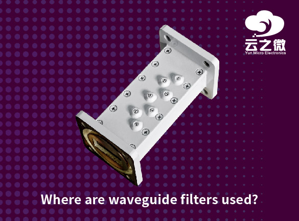
other
  • Bandpass Filter vs Low-Pass Filter: Which One Is Better for Signal Processing?
    The choice between a bandpass filter (BPF) and a low-pass filter (LPF) depends on your specific signal processing needs—neither is universally "better." Here’s a comparison to help decide: 1. Purpose & Frequency Response Low-Pass Filter (LPF): Allows frequencies below a cutoff frequency (f_c) to pass while attenuating higher frequencies.   Best for: Removing high-frequency noise. Anti-aliasing before ADC sampling. Smoothing signals (e.g., in audio or sensor data). Bandpass Filter (BPF): Allows frequencies within a specific range (f_lower to f_upper) to pass, rejecting both lower and higher frequencies. Best for: Extracting a specific frequency band (e.g., radio communications, EEG/ECG signals). Rejecting out-of-band interference (e.g., in wireless systems). 2. When to Use Which? Use an LPF if: You only care about the low-frequency components of a signal. Your goal is noise reduction (e.g., removing high-frequency hiss from audio). You need to prevent aliasing in data acquisition. Use a BPF if: Your signal of interest lies within a specific frequency range (e.g., extracting a 1 kHz tone in a noisy environment). You need to isolate a modulated carrier signal (e.g., in RF applications). You want to remove both DC offset and high-frequency noise (e.g., in biomedical signal processing). 3. Trade-offs Complexity: LPFs are simpler to design (e.g., RC, Butterworth). BPFs require tuning two cutoff frequencies and may need higher-order designs. Phase & Delay: Both filters introduce phase shifts, but BPFs may have more complex group delay characteristics. Noise Rejection: An LPF only removes high-frequency noise. A BPF removes noise outside its passband (better for selective applications). 4. Practical Example Audio Processing: Use an LPF to remove hiss/noise above 20 kHz. Use a BPF (300 Hz–3.4 kHz) for telephone voice signals. Wireless Communications: Use a BPF to select a specific channel (e.g., 2.4 GHz Wi-Fi band). Biomedical Signals: Use a BPF (0.5–40 Hz) for EEG to remove DC drift and high-frequency muscle artifacts.   Conclusion: Choose LPF for general noise reduction and preserving low-frequency content.   Choose BPF when isolating a specific frequency band or rejecting both low/high-frequency interference.   Yun Micro, as the professional manufacturer of rf passive components, can offer the cavity filters up 40GHz,which include band pass filter, low pass filter, high pass filter, band stop filter. Welcome to contact us: liyong@blmicrowave.com
  • What are the advantages of band pass filter?
    Bandpass filters (BPFs) are essential in signal processing and electronics, offering several advantages in various applications. Here are the key benefits: 1. Selective Frequency Isolation BPFs allow only a specific range of frequencies (the passband) to pass while attenuating frequencies outside this range (low and high frequencies). Useful for extracting desired signals from noise or interference. 2. Noise Reduction By blocking unwanted frequencies (both low and high), BPFs improve signal-to-noise ratio (SNR). Commonly used in communication systems (e.g., radio receivers) to isolate a particular channel. 3. Signal Clarity & Precision Enhances signal quality in audio processing, biomedical applications (e.g., EEG/ECG), and sensor data analysis. Removes DC offsets and high-frequency interference. 4. Flexibility in Design Can be implemented in analog (LC, RC, op-amp circuits) or digital (DSP algorithms) forms. Adjustable center frequency and bandwidth to suit different needs. 5. Prevents Aliasing in Sampling Systems In analog-to-digital conversion (ADC), BPFs can restrict input signals to the relevant frequency range, preventing aliasing. 6. Used in Modulation & Demodulation Essential in RF and wireless communications for selecting specific carrier frequencies. Helps in separating different channels in frequency-division multiplexing (FDM). 7. Biomedical & Scientific Applications Filters out artifacts in medical devices (e.g., removing 50/60 Hz power line interference from ECG signals). Used in spectroscopy and vibration analysis to focus on specific frequency components. 8. Improved System Performance Reduces interference in radar, sonar, and optical systems. Enhances audio quality in speaker systems by isolating mid-range frequencies Types & Their Advantages Active BPF (Opamp based): High precision, amplification, and tunability. Passive BPF (LC/RC): No power needed, simple design. Digital BPF (FIR/IIR): Programmable, no component drift. Disadvantages to Consider: Phase distortion near cutoff frequencies. Design complexity for very narrow or very wide bandwidths. Conclusion: Bandpass filters are crucial for isolating frequency bands, improving signal integrity, and reducing noise in electronics, communications, and scientific instruments. Their adaptability makes them indispensable in many technical fields. Yun Micro, as the professional manufacturer of rf passive components, can offer the cavity filters up 40GHz,which include band pass filter, low pass filter, high pass filter, band stop filter. Welcome to contact us: liyong@blmicrowave.com
  • What are the different types of RF filters?
    RF (Radio Frequency) filters are essential components in wireless communication systems, used to selectively pass or reject specific frequency ranges. They can be categorized based on frequency response, implementation technology, and application. Here are the main types: 1. Based on Frequency Response These define how the filter behaves in terms of frequency selection: Low-Pass Filter (LPF) - Allows frequencies below a cutoff frequency (f₀) to pass while attenuating higher frequencies. High-Pass Filter (HPF) - Allows frequencies above a cutoff frequency (f₀) to pass while attenuating lower frequencies. Band-Pass Filter (BPF) - Passes frequencies within a specific range (f₁ to f₂) and attenuates frequencies outside this band. Band-Stop Filter (BSF) / Notch Filter – Blocks a specific frequency range (f₁ to f₂) while allowing others to pass. All-Pass Filter - Passes all frequencies but introduces a phase shift without attenuation. 2. Based on Implementation Technology Different technologies are used to construct RF filters, each with unique characteristics: LC Filters - Use inductors (L) and capacitors (C); simple but bulky at lower frequencies. SAW Filters (Surface Acoustic Wave) - Use piezoelectric materials for high-frequency applications (MHz-GHz range). BAW Filters (Bulk Acoustic Wave) - Similar to SAW but operate at higher frequencies with better power handling (used in 5G). Ceramic Filters - Use ceramic resonators for compact, stable performance in wireless systems. Cavity Filters - Use waveguide cavities for high-power applications (e.g., base stations, radar). MMIC Filters (Monolithic Microwave ICs) - Integrated into semiconductor chips for compact RF systems. Dielectric Resonator Filters - Use high-permittivity materials for high-Q factor performance. 3. Based on Response Characteristics Butterworth Filter - Maximally flat passband, moderate roll-off. Chebyshev Filter - Steeper roll-off but has ripple in passband/stopband. Elliptic (Cauer) Filter - Sharpest transition but ripple in both passband and stopband. Bessel Filter - Preserves phase but has slower roll-off. 4. Based on Tuning Mechanism Fixed Filters - Designed for a specific frequency range (non-adjustable). Tunable Filters - Can adjust center frequency or bandwidth dynamically (used in software-defined radios). Applications of RF Filters Wireless Communication (5G, Wi-Fi, LTE) - Band selection and interference rejection. Radar & Satellite Systems - Signal isolation and noise reduction. Medical Devices (MRI, RF Ablation) - Frequency control for safety. Defense & Aerospace - Secure and reliable signal transmission. Yun Micro, as the professional manufacturer of rf passive components, can offer the cavity filters up 40GHz,which include band pass filter, low pass filter, high pass filter, band stop filter. Welcome to contact us: liyong@blmicrowave.com
  • What is the expected lifespan of an LTCC filter in harsh operating conditions?
    The expected lifespan of Low-Temperature Co-Fired Ceramic (LTCC) filter in harsh operating conditions depends on several factors, including environmental stressors, electrical load, and material robustness. Here’s a general assessment: Key Factors Affecting LTCC Filter Lifespan in Harsh Conditions: 1. Temperature Extremes LTCC filters typically operate in 55°C to +125°C ranges. Prolonged exposure to >150°C can degrade materials, reducing lifespan. Thermal cycling (repeated heating/cooling) may cause cracking or delamination. 2. Humidity & Corrosion LTCC materials are generally moisture-resistant, but harsh salt fog or acidic environments can corrode electrodes. Hermetic sealing or conformal coatings can extend lifespan. 3. Mechanical Stress & Vibration LTCC is brittle, excessive shock/vibration may cause microfractures. Proper mounting and shock absorption help mitigate this. 4. Electrical Stress High power RF signals or voltage surges can accelerate aging. Operating near maximum rated power may reduce longevity. 5. Frequency of Use Continuous high-frequency operation may cause gradual performance degradation. Estimated Lifespan in Harsh Conditions: Standard Conditions: 10–20 years (typical for LTCC components). Harsh Conditions (high temp, humidity, vibration): 5–10 years, depending on mitigation strategies. Extreme Conditions : 3–7 years, with possible derating or redundancy. Mitigation Strategies to Extend Lifespan: Use hermetic packaging for moisture resistance. Apply thermal management (heat sinks, airflow). Ensure mechanical stabilization (damping, secure mounting). Operate below maximum power/voltage ratings. Select high-reliability LTCC formulations (e.g., DuPont 951, Heraeus HTCC/LTCC blends). Yun Micro, as the professional manufacturer of rf passive components, can offer the cavity filters up 40GHz,which include band pass filter, low pass filter, high pass filter, band stop filter. Welcome to contact us: liyong@blmicrowave.com
  • What are the challenges in designing LC low pass filters for ultra-low frequency applications?
    Designing LC low-pass filters for ultra-low frequency (ULF) applications (typically below 1 Hz) presents several unique challenges due to the impracticality of passive components at such frequencies. Below are the key challenges: 1. Impractically Large Inductor (L) and Capacitor (C) Values The cutoff frequency (\(f_c\)) of an LC low-pass filter is given by: For ultra-low frequencies (e.g., 0.1 Hz), L and C must be extremely large (e.g., Henries and Farads), making passive components bulky, expensive, and lossy. 2. Component Non-Idealities Inductor Issues: Large inductors suffer from high DC resistance (DCR), leading to significant I²R losses. Core saturation and nonlinearity in large inductors distort signal behavior. Parasitic capacitance becomes problematic, affecting high-frequency rejection. Capacitor Issues: Electrolytic capacitors (needed for large capacitance) have high ESR (Equivalent Series Resistance), reducing filter efficiency. Leakage current and dielectric absorption introduce errors in signal integrity. 3. Sensitivity to Component Tolerances Small variations in L or C (due to manufacturing tolerances, temperature drift, or aging) cause significant shifts in the cutoff frequency. Achieving tight tolerance in ultra-large components is difficult and expensive. 4. Poor Transient Response & High Time Constants The filter's time constant (τ = L/R or RC) becomes extremely large, leading to: Slow settling times (undesirable for step responses). Excessive phase delays, making the filter unsuitable for real-time control systems. 5. Noise and Interference Susceptibility At ultra-low frequencies, 1/f noise (flicker noise) dominates, degrading signal quality. Large inductors and capacitors act as antennas, picking up electromagnetic interference (EMI). 6. Alternative Solutions Often Required Due to impractical passive components, designers often resort to: Active filters (using op-amps, OTAs, or gyrators to simulate large L/C values). Switched-capacitor filters (for programmable cutoff frequencies). Digital filtering (DSP-based approaches for precise control). Conclusion: While LC filters are simple and effective for higher frequencies, their use in ultra-low frequency applications is limited by component size, losses, tolerances, and noise. Active filtering techniques or digital signal processing are often better alternatives for such cases. Yun Micro, as the professional manufacturer of rf passive components, can offer the cavity filters up 40GHz,which include band pass filter, low pass filter, high pass filter, band stop filter. Welcome to contact us: liyong@blmicrowave.com
  • How to choose the right filter type (LTCC, LC, cavity, or waveguide) for RF applications?
    Choosing the right filter type for RF applications depends on several key parameters and application requirements. Here’s a structured approach to selecting between LTCC, LC, Cavity, and Waveguide filters: 1. Frequency Range LTCC (LowTemperature Cofired Ceramic): Best for 500 MHz – 6 GHz (e.g., WiFi, 5G sub6 GHz, IoT). Limited performance at higher frequencies due to parasitic effects. LC (Lumped Element): Suitable for DC – 3 GHz (lower frequencies). Suffers from poor Qfactor at higher frequencies. Cavity Filters: Ideal for 1 GHz – 40 GHz (cellular base stations, radar, satellite). High Qfactor, good for narrowband applications. Waveguide Filters: Best for 10 GHz – 100+ GHz (mmWave, radar, aerospace). Excellent performance at extremely high frequencies. 2. Insertion Loss & QFactor LTCC: Moderate Q (~100300), insertion loss ~13 dB. LC: Low Q (~50200), higher insertion loss (~25 dB). Cavity: High Q (~1,00010,000), low insertion loss (~0.11 dB). Waveguide: Very high Q (~10,000+), ultralow loss (~0.050.5 dB). 3. Size & Integration LTCC: Very compact, surfacemountable, good for integrated modules. LC: Small but suffers from parasitic effects at high frequencies. Cavity: Bulky, used in base stations and highpower systems. Waveguide: Largest, used in aerospace. 4. Power Handling LTCC & LC: Low to medium power (up to a few watts). Cavity: High power (10s to 100s of watts). Waveguide: Extremely high power (kW range). 5. Cost & Manufacturing LTCC: Low to medium cost, massproducible. LC: Cheapest but limited performance. Cavity: Higher cost due to precision machining. Waveguide: Most expensive, used in highend applications. 6. Application Examples: Decision Flowchart: 1. Frequency > 10 GHz? → Waveguide (if power & budget allow). 2. Need ultralow loss & high power? → Cavity. 3. Small size & moderate performance? → LTCC. 4. Lowcost, lowfrequency? → LC. Final Recommendation: 5G/WiFi (Sub6 GHz, compact): LTCC. Cellular Base Stations (High power, low loss): Cavity. mmWave/Radar (Extremely high frequency): Waveguide. Consumer Electronics (Low cost, <3 GHz): LC. Yun Micro, as the professional manufacturer of rf passive components, can offer the cavity filters up 40GHz,which include band pass filter, low pass filter, high pass filter, band stop filter. Welcome to contact us: liyong@blmicrowave.com
  • Standard vs Customized Filters: Which One Is Right for Your Project?
    When working on electronic signal processing, communication systems, or audio equipment projects, choosing between standard filters and custom filters depends on specific technical requirements, budget constraints, and performance needs. Here’s a comparative analysis of the two options: 1. Standard Filters (Off-the-Shelf Filters) Ideal for: General signal processing needs, such as routine filtering, noise reduction, or frequency band selection. ✔ Advantages: Cost-effective – Mass-produced, making them more affordable. Ready to use – No design lead time, speeding up project timelines. Stable performance – Tested for common applications with reliable results. Good compatibility – Typically adhere to industry-standard interfaces (e.g., SMA, BNC). ✖ Disadvantages: Limited flexibility – Fixed parameters like frequency response and stopband attenuation cannot be adjusted. Performance constraints – May not meet high-precision or specialized application requirements. Typical Applications: Audio signal processing (low-pass, high-pass, band-pass filtering) Radio communications (preselect filters, anti-aliasing filters) Laboratory test equipment (standard frequency band filtering) 2. Custom Filters Ideal for: Specialized frequency response requirements, harsh environments, or high-performance systems. ✔ Advantages: Customizable parameters – Precise design of cutoff frequency, roll-off slope, group delay, etc. Optimized performance – Tailored to specific interference or signal characteristics (e.g., ultra-narrowband, steep transition bands). Adapts to unique needs – Supports high-temperature, radiation-resistant, or miniaturized designs. Integrated solutions – Can be embedded into system PCBs or combined with other functional modules. ✖ Disadvantages: Higher cost – Requires dedicated design, simulation, and debugging, significantly increasing development expenses. Longer lead time – Design to delivery may take weeks or even months. Supplier dependency – Future modifications or maintenance may require manufacturer support. Typical Applications: Military radar/electronic warfare (anti-jamming, ultra-wideband filtering) Satellite communications (high-frequency, low-loss filtering) Medical equipment (e.g., MRI signal processing) High-precision instruments (quantum computing, astronomical observation) Selection Recommendations: Choose standard filters if your project has common requirements (e.g., audio noise reduction, standard RF filtering) and off-the-shelf products meet your specifications. Opt for custom filters if: Standard products cannot meet your frequency response, size, or environmental requirements; Your system demands extreme performance (e.g., <0.1dB ripple); Deep integration with other hardware (e.g., System-on-Chip, SoC) is needed. Yun Micro, as the professional manufacturer of rf passive components, can offer the cavity filters up 40GHz,which include band pass filter, low pass filter, high pass filter, band stop filter. Welcome to co...
  • Can cavity band pass filters be used in space applications? If yes, what considerations are necessary?
    Cavity bandpass filters can be used in space applications, but they require special considerations due to the harsh space environment. Here are the key factors to address: 1. Material Selection & Thermal Stability Low Outgassing Materials: Space-grade materials (e.g., Invar, titanium, or specially coated aluminum) must be used to minimize outgassing in vacuum, which could contaminate sensitive optics or electronics. Thermal Expansion Control: The filter must maintain performance across extreme temperature swings (e.g.,150°C to +150°C). Materials with matched coefficients of thermal expansion (CTE) should be chosen to prevent mechanical deformation. 2. Vibration & Mechanical Robustness Must survive high launch vibrations (typically 10–2000 Hz, 10–20 G RMS). Reinforced structures or damping mechanisms may be needed to prevent microphonics or detuning. 3. Radiation Hardness Some dielectric or ferromagnetic materials can degrade under ionizing radiation. Radiation-resistant coatings or materials (e.g., alumina, sapphire) should be considered. 4. Vacuum Compatibility No organic adhesives that could outgas; instead, use brazing or welding. Avoid trapped volumes that could cause pressure differential issues. 5. Frequency Stability & Tuning Thermal shifts can detune the filter; temperature compensation (e.g., using dielectric rods with opposite CTE) may be required. Some missions may require tunable filters (e.g., piezoelectric actuators) for adaptability. 6. Insertion Loss & Power Handling Minimize loss (critical for weak signals in deep space comms). High-power applications (e.g., satellite transmitters) may need enhanced heat dissipation. 7. Testing & Qualification Thermal Cycling: Verify performance across mission temperature ranges. Vibration Testing: Simulate launch conditions per standards like NASA-STD-7003 or ECSS-E-10-03. Outgassing Tests: Meet NASA ASTM E595 or ESA ECSS-Q-ST-70-02. Example Space Applications Satellite communication (e.g., X/Ku/Ka-band filters). Deep-space probes (narrowband filters for high-selectivity comms). Earth observation (spectral filtering in hyperspectral imagers). Conclusion Cavity bandpass filters are viable in space but require rigorous design, material selection, and testing to ensure reliability. Custom solutions from space-qualified manufacturers (e.g., ESA/NASA-approved vendors) are often necessary. Yun Micro, as the professional manufacturer of rf passive components, can offer the cavity filters up 40GHz,which include band pass filter, low pass filter, high pass filter, band stop filter. Welcome to contact us: liyong@blmicrowave.com
1 2 3 4 5 6 7 8

A total of 8 pages

Subscribe to Our Newsletter
Sign up to our newsletter for the Microwaves & RF.

Leave A Message

Leave A Message
If you are interested in our products and want to know more details,please leave a message here,we will reply you as soon as we can.

Home

Products

skype