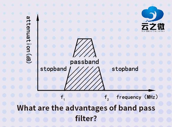
other
  • What Are the Benefits of Using a Customized Filter for Your RF Application?
    Customized RF filters offer three key advantages over off-the-shelf solutions. First, they provide exact frequency response tailoring - precise control over passband/stopband ranges, rejection slopes, and insertion loss - ensuring optimal interference suppression for your specific application. Second, they enable superior physical integration, whether for extreme environments (high temp/power), compact layouts, or multi-band systems where generic filters fall short.  Finally, while requiring higher initial investment, they deliver long-term value through enhanced reliability, perfect system compatibility, and reduced need for additional filtering stages - particularly critical for 5G, defense, and aerospace applications where performance margins matter most.   Yun Micro, as the professional manufacturer of rf passive components, can offer the cavity filters up 40GHz,which include band pass filter, low pass filter, high pass filter, band stop filter.   Welcome to contact us: liyong@blmicrowave.com
  • How to Design a Bandreject Filter for High-Frequency Applications?
    Designing a bandreject filter (also called a notch filter) for high-frequency applications requires careful consideration of frequency range, rejection depth, circuit topology, and real-world component behavior at RF/microwave frequencies. Below is a structured approach to designing such a filter.   1. Define Key Specifications Center frequency (f₀): The frequency to be rejected (e.g., 2.4 GHz for Wi-Fi interference). Bandwidth (BW): The range of frequencies to attenuate (e.g., ±100 MHz around f₀). Rejection depth: Desired attenuation in the stopband (e.g., >30 dB). Impedance matching: Typically 50Ω (RF systems) or 75Ω (video/telecom). Insertion loss in passband: Minimize signal loss outside the rejected band. 2. Choose a Filter Topology A. LC Resonant Circuits (Suitable for MHz to Low GHz) Series LC Notch: Blocks signals at resonance (high impedance at f₀). Best for narrowband rejection. Parallel LC Notch: Shunts unwanted signals to ground at f₀. Useful in shunt-stub configurations. Limitations: Parasitic capacitance/inductance affects performance at high frequencies. B. Transmission Line / Distributed Filters (GHz Range) Quarter-wave (λ/4) Stub Filters: Open or short-circuited stubs create impedance mismatches at f₀. Example: A parallel open stub rejects signals at λ/4 resonance. Defected Ground Structure (DGS): Etched patterns on PCB ground plane act as a bandstop element. Advantage: Better performance in microwave frequencies (e.g., 5G, radar). C. Active Notch Filters (For Lower Frequencies, <100 MHz) Uses op-amps with feedback networks (e.g., Twin-T, Wien bridge). Limited by op-amp bandwidth at higher frequencies.   3. High-Frequency Component Selection Inductors (L): Use air-core or high-Q RF inductors to minimize losses. Avoid ferrite cores at GHz (high parasitic capacitance). Capacitors (C): NP0/C0G ceramic or RF capacitors for stability. Minimize equivalent series inductance (ESL). PCB Layout Considerations: Short traces to reduce parasitic inductance. Use ground planes and controlled impedance lines.   4. Design Example (LC Parallel Notch Filter for 2.4 GHz) Calculate L & C for resonance at f₀: Example: For 2.4 GHz, choose L = 2.2 nH, then C ≈ 2 pF. Place the LC in shunt (parallel) with the signal path. At 2.4 GHz, the LC tank creates a low-impedance path to ground, attenuating the signal. Simulate & Optimize (e.g., in Keysight ADS or Ansys HFSS): Account for PCB parasitics (trace inductance, via effects).   5. Validation & Tuning  Measure with a Vector Network Analyzer (VNA): Check S21 (transmission) for rejection depth. Verify S11 (reflection) for impedance matching. Adjustments: Fine-tune L/C values or stub lengths for optimal performance. Key Challenges in High-Frequency Design Parasitics: Stray capacitance/inductance shifts f₀. Component tolerance...
  • How Do Notch Filters Help in Eliminating Interference in RF Circuits?
    Notch filters are highly effective in eliminating interference in RF (Radio Frequency) circuits by selectively attenuating a narrow band of unwanted frequencies while allowing the rest of the signal to pass with minimal loss. Here’s how they help: 1. Targeted Frequency Rejection l Notch filters are designed to block a specific narrow frequency band (the "notch") where interference occurs, such as: l Unwanted signals (e.g., harmonics, spurious emissions). l External interference (e.g., power line noise at 50/60 Hz or RFI from nearby transmitters). l Co-channel interference in communication systems. 2. Preserving Desired Signals Unlike low-pass or high-pass filters, notch filters do not affect frequencies outside the stopband, ensuring minimal distortion to the rest of the RF signal. This is crucial in applications like Wi-Fi, cellular communications, and radar, where signal integrity is critical. 3. Improving Signal-to-Noise Ratio (SNR) By removing strong interfering tones (e.g., a jammer signal or clock harmonics), notch filters enhance the SNR, leading to better demodulation and data recovery. 4. Common Applications l Wireless Communications: Removing interfering signals from adjacent channels. l Audio & RF Systems: Eliminating power line hum (50/60 Hz) in audio or RF circuits. l Radar & Satellite Systems: Suppressing jamming signals or spurious emissions. l Medical & Scientific Instruments: Filtering out noise in sensitive measurements. Types of Notch Filters: l LC Notch Filters: Use inductors and capacitors to create a resonant null at the target frequency. l Active Notch Filters: Incorporate op-amps for sharper rejection and tunability. l SAW/BAW Filters: Surface Acoustic Wave (SAW) or Bulk Acoustic Wave (BAW) filters for high-frequency applications. l Digital Notch Filters: Used in DSP-based systems for adaptive interference cancellation. Design Considerations l Center Frequency (f₀): Must match the interference frequency. l Bandwidth (Q Factor): Determines how narrow or wide the rejection band is. l Insertion Loss: Should be minimal outside the notch to avoid signal degradation. Conclusion Notch filters are essential in RF circuits for precisely eliminating interference without disrupting the desired signal, making them invaluable in communication, radar, and electronic warfare systems. Yun Micro, as the professional manufacturer of rf passive components, can offer the cavity filters up 40GHz,which include band pass filter, low pass filter, high pass filter, band stop filter. Welcome to contact us: liyong@blmicrowave.com
  • Bandpass Filter vs Low-Pass Filter: Which One Is Better for Signal Processing?
    The choice between a bandpass filter (BPF) and a low-pass filter (LPF) depends on the specific requirements of your signal processing application. Neither is universally "better"—each serves different purposes. Here’s a comparison to help you decide: 1. Purpose & Frequency Response Low-Pass Filter (LPF): Allows frequencies below a cutoff frequency (fc) to pass while attenuating higher frequencies. Used to remove high-frequency noise, smooth signals, or prevent aliasing in ADC systems. Example applications: Audio bass enhancement, anti-aliasing in data acquisition, DC restoration. Bandpass Filter (BPF): Allows a specific range of frequencies (between a lower fc1 and upper fc2) to pass while blocking frequencies outside this range. Used to isolate a signal of interest in a noisy environment or extract a modulated carrier frequency. Example applications: RF communication (e.g., AM/FM radio tuning), EEG/ECG signal extraction, vibration analysis. 2. When to Use Which? Use an LPF if: You only care about low-frequency components (e.g., removing high-frequency noise). Your signal is baseband (centered around 0 Hz). You need simpler design & lower computational cost (fewer components than BPF). Use a BPF if: Your signal lies in a specific frequency band (e.g., a radio channel or sensor signal). You need to reject both low and high-frequency interference (e.g., 50/60 Hz power line noise + RF noise). You’re working with modulated signals (e.g., filtering an AM/FM band). 3. Trade-offs 4. Practical Example LPF: In an ECG signal, an LPF (e.g., 150 Hz cutoff) removes muscle noise and RF interference. BPF: In a wireless receiver, a BPF (e.g., 88–108 MHz for FM radio) isolates the desired station while rejecting others. Conclusion Choose LPF for general-purpose noise removal and DC/low-frequency signal extraction. Choose BPF when you need to isolate a specific frequency band or reject out-of-band interference. If your signal has both requirements (e.g., needing to pass low frequencies but also block very low-frequency drift), a combination of HPF + LPF (making a BPF) might be optimal. Yun Micro, as the professional manufacturer of rf passive components, can offer the cavity filters up 40GHz,which include band pass filter, low pass filter, high pass filter, band stop filter. Welcome to contact us: liyong@blmicrowave.com
  • How to Choose the Right Bandpass Filter for Your Communication System?
    Selecting the right bandpass filter for a communication system requires careful consideration of multiple key factors to ensure signal quality, suppress interference, and meet system performance requirements. Below are the main selection criteria: 1. Determine Key Parameters Center Frequency (f₀): The filter's passband center frequency must match the signal frequency range. Bandwidth (BW): Choose based on the signal bandwidth to allow useful signals while rejecting out-of-band noise. Insertion Loss: Ideally as low as possible (typically <3dB) to avoid excessive signal attenuation. Stopband Rejection: Must sufficiently suppress adjacent-channel interference or harmonics (typically >30dB). Passband Ripple: Should be minimal (e.g., <0.5dB) to prevent signal distortion. 2. Select the Filter Type LC Filters: Suitable for low frequencies (<1GHz), cost-effective but bulky. SAW/BAW Filters: High-Q, used in high-frequency applications (hundreds of MHz to several GHz), such as 5G and Wi-Fi. Cavity Filters: High power handling, low loss, ideal for base stations and radar systems. Dielectric Filters: Compact, high-Q, suitable for millimeter-wave communications. 3. Consider System Requirements Communication Standard (e.g., 5G, Wi-Fi, LTE) determines frequency range and rejection requirements. Power Handling: High-power systems (e.g., base stations) require filters with high power tolerance. Temperature Stability: Harsh environments demand filters with low thermal drift (e.g., ceramic dielectric filters). Size & Integration: Mobile devices need miniaturized filters (e.g., BAW, IPD filters). 4. Verification & Testing Use a network analyzer to measure S-parameters (S21 for passband response, S11 for impedance matching). Check group delay to ensure it doesn’t degrade signal integrity (critical for digital modulation systems). 5. Typical Application Examples 5G Sub-6GHz: BAW or dielectric filters, 100-400MHz bandwidth, high rejection. Wi-Fi 6E: SAW/BAW filters, 6GHz center frequency, strong 5GHz interference suppression. Satellite Communications: Cavity filters, high power handling, low insertion loss. By evaluating frequency, bandwidth, loss, rejection, size, and cost, you can select the optimal bandpass filter. For specialized needs, consult filter manufacturers for custom solutions. Yun Micro, as the professional manufacturer of rf passive components, can offer the cavity filters up 40GHz,which include band pass filter, low pass filter, high pass filter, band stop filter. Welcome to contact us: liyong@blmicrowave.com
  • What is the role of LTCC filters in 5G technology?
    LTCC filters are critical components in 5G RF front-end modules, enabling precise frequency selection and interference suppression across Sub-6GHz and mmWave bands. Their multilayer ceramic design offers miniaturization, low insertion loss, and thermal stability, making them ideal for compact 5G devices and base stations. Additionally, LTCC technology supports carrier aggregation and massive MIMO by providing high Q-factor and multi-band filtering in a single integrated package. Comparison with Other Filter Technologies: Yun Micro, as the professional manufacturer of rf passive components, can offer the cavity filters up 40GHz,which include band pass filter, low pass filter, high pass filter, band stop filter.   Welcome to contact us: liyong@blmicrowave.com
  • What are the environmental factors affecting the reliability of cavity band pass filters?
    The reliability of cavity bandpass filters is affected by various environmental factors, mainly including:   Temperature variations: Temperature fluctuations cause expansion or contraction of cavity materials, altering resonator dimensions and thereby affecting center frequency and bandwidth characteristics.   Humidity and condensation: High humidity environments may lead to internal component corrosion or surface oxidation, and in extreme cases cause condensation, significantly impacting filter performance.   Mechanical vibration and shock: Physical vibrations may cause tuning element displacement or internal connection loosening, changing filter characteristics.   Pressure changes: For designs with insufficient airtightness, pressure variations may alter the dielectric properties inside the cavity.   Dust and contaminants: Particle accumulation may change surface conductivity characteristics or cause short circuits between components.   Electromagnetic interference (EMI): Strong electromagnetic fields may induce nonlinear effects or saturation in the filter.   Salt spray (coastal environments): Accelerates corrosion of metal components, particularly significantly affecting aluminum cavities. Yun Micro, as the professional manufacturer of rf passive components, can offer the cavity filters up 40GHz,which include band pass filter, low pass filter, high pass filter, band stop filter.   Welcome to contact us: liyong@blmicrowave.com
  • What materials are used in manufacturing LTCC filters, and why are they beneficial?
    Low-Temperature Co-Fired Ceramic (LTCC) filters are widely used in RF and microwave applications due to their excellent performance and miniaturization capabilities. The materials used in manufacturing LTCC filters include:   1. Ceramic Substrate (Glass-Ceramic Composite) Primary Components: Alumina (Al₂O₃), silica (SiO₂), and glass-forming oxides (e.g., borosilicate glass). Why Beneficial? Low Sintering Temperature (~850–900°C): Allows co-firing with high-conductivity metals like silver (Ag) or gold (Au). Thermal Stability: Maintains structural integrity under thermal stress. Low Dielectric Loss (tan δ ~0.002–0.005): Enhances signal integrity at high frequencies.   2. Conductive Materials (Electrodes & Traces) Silver (Ag), Gold (Au), or Copper (Cu): Why Beneficial? High Conductivity: Minimizes insertion loss in RF/microwave applications. Compatibility with LTCC Processing: These metals do not oxidize excessively at LTCC sintering temperatures.   3. Dielectric Additives (For Tuning Properties) TiO₂, BaTiO₃, or ZrO₂: Why Beneficial? Adjustable Permittivity (εᵣ ~5–50): Enables compact filter designs by controlling wavelength scaling. Temperature Stability: Reduces frequency drift with temperature variations.   4. Organic Binders & Solvents (Temporary Processing Aids) Polyvinyl Alcohol (PVA), Acrylics: Why Beneficial? Facilitates Tape Casting: Allows the ceramic to be formed into thin green tapes before firing. Burn Out Cleanly: No residual ash after sintering.   Key Benefits of LTCC Filters: Miniaturization: Multilayer integration reduces footprint. High-Frequency Performance: Low loss and stable dielectric properties up to mmWave frequencies. Thermal & Mechanical Robustness: Suitable for harsh environments (automotive, aerospace). Design Flexibility: 3D structures with embedded passives (inductors, capacitors) are possible. LTCC technology is favored in 5G, IoT, and satellite communications due to these material advantages. Yun Micro, as the professional manufacturer of rf passive components, can offer the cavity filters up 40GHz,which include band pass filter, low pass filter, high pass filter, band stop filter.   Welcome to contact us: liyong@blmicrowave.com
1 ... 6 7 8 9 10 11

A total of 11 pages

Subscribe to Our Newsletter
Sign up to our newsletter for the Microwaves & RF.

Leave A Message

Leave A Message
If you are interested in our products and want to know more details,please leave a message here,we will reply you as soon as we can.

Home

Products

skype